
Exploring the Raspberry Pi through real-world projects
Embedded Systems
The second and third projects employ the Raspberry Pi as an embedded system on a network – without a keyboard, mouse, or monitor, but with LAN/WLAN access. On such a system, you can read out the messages on startup with a terminal on the serial port. If an error occurs in the network configuration, you won't be able to access the system through SSH, so connecting directly through a monitor and keyboard is the only way to log on to the system and correct the error. Therefore, you would be well advised to enable the serial interface (see the box titled "Enabling the Serial Interface"). Access with SSH via the network should always be the first choice; access via the serial interface should only be used as a back door for emergencies.
Enabling the Serial Interface
Equipping the Raspberry Pi with a serial interface requires a bit of tinkering in advance: The TXD and RXD signals from the UART of the SoC are sent to pins 8 and 10 of the P1 double-row header between the TV output and SD card slot (Figure 1). However, the signals are still at the I/O level of the SoC with 3.3 volts. With a level shifter, you can move them to the standard RS232 serial range. For this, you can use the MAX3232CP IC, for example.
 Figure 1: Between the TV output and SD card slot, you will find the header to which the circuit board sends the TXD and RXD signals for a serial interface.
As a terminal program on the PC, Minicom can be used. With the minicom -s command, you can make the minimal changes to the settings that are necessary. For example, the serial port can be represented by either the /dev/ttyS or /dev/ttyUSB device file.
The data rate (115,200bps) and the data format (8N1) are preset. Make sure that neither Hardware Flow Control nor Software Flow Control is used by the software. The minicom -o command prevents the program from executing the sequences for initializing on startup and connects you directly to the console.
The next step in building the embedded system is to set up a network connection; in this example, I'll connect through a WLAN. The default installation of Raspbian already contains the firmware packages of popular WLAN sticks, as well as the client program wpa_supplicant. To see whether the WLAN stick is active, connect the hardware and search for the corresponding reaction of the kernel in the syslog.
Now the only thing left to do is set up wpa_supplicant for an access point. In a network with a DHCP server in the router, you will find the essential data in the report provided by iwlist scanning. You then modify the configuration file /etc/wpa_supplicant/wpa_supplicant.conf, as shown in Listing 2, and /etc/network/interfaces, as shown in Listing 3. Finally, start the connection with sudo ifup wlan0.
Listing 3
Modify /etc/network/interfaces
auto wlan0
iface wlan0 inet dhcp
wpa-conf /etc/wpa_supplicant/wpa_supplicant.conf
Listing 2
Modify Config File
ctrl_interface=/var/run/wpa_supplicant
eapol_version=1
ap_scan=1
network={
  ssid="(E)SSID"
  scan_ssid=1
  proto=WPA (or RSN for WPA2)
  key_mgmt=WPA-PSK
  pairwise=TKIP (or CCMP)
  group=TKIP (or CCMP)
  psk="key"
}
Project 2: Access Point
Raspberry Pi itself can also serve as an access point (Figure 2). In that case, it simply forwards everything the WLAN stick receives directly to the LAN port – sort of like a bridge. That is why this setup is called "bridged mode." In this way, you can increase the range of an existing wireless network.
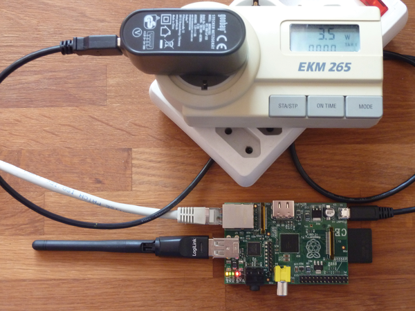 Figure 2: The Raspberry Pi operating as an access point – with a power consumption of only 3.5 Watts.
The configuration is done in two steps. In the first step, you set up the direct WLAN access with the hostapd daemon. However, note that hostapd is not fully compatible with all WLAN sticks. Look online for a list of supported hardware [9]. In the second step, you then configure the packet forwarding between the two interfaces. The necessary packages are installed with:
$ sudo apt-get install hostapd bridge-utils
Configure the WLAN access point in three steps: First, you insert the following line into /etc/default/hostap:
DAEMON_CONF=/etc/hostapd/hostapd.conf
Then add the contents of Listing 4 to the /etc/hostapd/hostapd.conf file, modifying it to fit the local environment if necessary. A sample configuration for the /etc/network/interfaces file is found in Listing 5. Listing 6 shows how to start the access point and network bridge.
Listing 6
Start Access Point
$ sudo service hostapd start
$ sudo brctl addbr myBridge
$ sudo brctl addif myBridge eth0
$ sudo brctl addif myBridge wlan0
$ sudo ifconfig myBridge up
Listing 5
Network Interfaces
auto wlan0
iface wlan0 inet static
address 192.168.128.1
netmask 255.255.255.0
broadcast 192.168.128.255
Listing 4
Add to hostapd.conf
ctrl_interface=/var/run/hostapd
ctrl_interface_group=0
driver=nl80211 # according to driver support
macaddr_acl=0
auth_algs=3
ignore_broadcast_ssid=0
wpa=2      # for WPA2 with PSK
wpa_key_mgmt=WPA-PSK
rsn_preauth=1
rsn_preauth_interfaces=wlan0
rsn_pairwise=CCMP
wpa_passphrase=password
interface=wlan0
hw_mode=g
channel=11 # a free or weak channel
ssid=(E)SSID
Power consumption is lower with LAN operation. Depending on the distance between the WLAN stations and the data volume transferred, energy consumption for a WLAN client or access point fluctuated between 3.3 and 3.8 watts, whereas under LAN operation, consumption was around 2.9 watts. If both interfaces were active, the value was between 3.5 and 4 watts.
Project 3: Temperature Controller
In addition to serving as a flexible access point, the Raspberry Pi is also excellent for controlling simple processes. The following example takes cyclical temperature measurements of its environment and, depending on the value, signals the results visually with two LEDs. At temperatures above 25 degrees Celsius, the controller turns on the red LED; at less than 22 degrees Celsius, it turns on the green LED. Both lights are turned on at values between the two (Figure 3). Of course, this project is intended as a proof-of-concept experiment. In an actual, real-world implementation, the controller might take some other action, such as starting a space heater or closing the curtains, rather than simply turning on an LED.
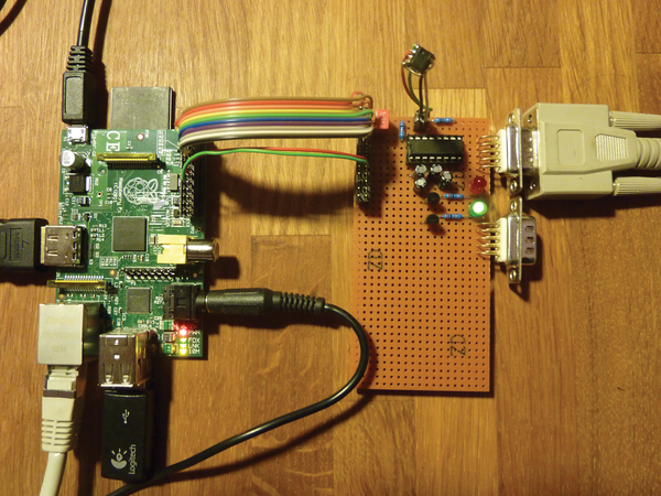 Figure 3: The Raspberry Pi with an expansion board as a temperature monitor. The green light on the expansion board confirms that the temperature is below 22 degrees Celsius. The IC LM75 sensor protrudes from the board on four wires. The 16-pin DIL IC is the MAX3232CPE RS232 serial transceiver.
The temperature controller unit requires some additional hardware that occupies a separate expansion board. You need the following parts: the LM75 IC as a temperature sensor and the MAX3232CPE IC, including four 0.47µF electrolytic capacitors, as a transceiver for the serial interface (UART), along with a nine-pin D-sub connector or a socket for PCB mounting and an interface cable. Also, you need two LEDs, red and green, each with a 22Ohm series resistor and an NPN transistor (e.g., the BC237) as a driver, as well as two pull-up resistors with 10kOhm for the I2C bus. Miscellaneous material, such as a breadboard, power strip, flat-ribbon cable, and decoupling capacitors, serve as the foundation.
The popular LM75 module serves as the temperature sensor and is connected to the I2C bus. The machine controls the two LEDs via two GPIO pins and a transistor stage. The wiring is simple – you can refer to a template on the Web.
Actually, the SoC has two master interfaces on the I2C bus, whose output is also found in the syslog, but only one of the two is available on the double-row header (P1-03 and P1-05) – the one with the bus-ID 0. You can enable the I2C bus by installing the two drivers i2c-bcm2708 and i2c-dev.
To do this, remove the i2c-bcm2708 driver from the list of drivers that are not to be loaded in /etc/modprobe.d/raspi-blacklist.conf. You specify the i2c-dev driver, which creates the interface in the /dev device directory, in /etc/modules. The bus will be active once the system has been restarted. To activate the bus without rebooting, execute the modprobe i2c-bcm2708 I2C-dev command.
So that you can perform transactions on the I2C bus as a normal user, you will first need to install some corresponding tools and set group permissions:
$ sudo apt-get install i2c-tools
$ sudo addgroup pi i2c
The addresses under which the modules are to be found is revealed by the values found in the output returned by
i2cdetect -y 0
Depending on how you have wired the three address pins of the LM75, the output will contain exactly one value in the hexadecimal range from 0x48 to 0x4f. You then read out the 2-byte temperature word of the LM75 at register address 0 with the command:
$ i2cget -y 0 I2C bus_address register_address w
The data sheet of the module will be of help for converting the cryptic value returned (example: 0x8015) to the corresponding temperature.
Python is a suitable a software environment for the controller, since class libraries already exist for the Raspberry Pi for accessing the I2C bus and the GPIO pins. This example used two libraries [10] [11]. Listing 7 shows the installation of the packages and libraries. The program itself is very simple (Listing 8): It reads the sensor value (line 15) in a cycle of five seconds and converts the sensor reading into the temperature value (line 16). The program then turns the two LEDs on or off accordingly.
Listing 8
Controller Program
Listing 7
Python Packages and Libraries
$ sudo apt-get install git python3 python-pip python-virtualenv
$ git clone https://github.com/quick2wire/quick2wire-gpio-admin.git
$ git clone https://github.com/quick2wire/quick2wire-python-api.git
$ cd quick2wire-gpio-admin
$ make
$ sudo make install
$ sudo adduser pi gpio
$ virtualenv TEMPCONTROL
$ source TEMPCONTROL/bin/activate
$ cd quick2wire-python-api
$ sudo python3 setup.py install
The different designations for the GPIO pins are a little confusing. The red and green LEDs are GPIO23/GPIO24, according to the header, but they are also connected to P1-16/P1-18. The first designation corresponds to the BCM2835 documentation and the values from the kernel. However, the Python libraries follow the second nomenclature.
You will need to provide the script with the necessary permissions for execution. After starting, it will continuously output the values measured to the console with each update of the LEDs.
« Previous 1 2 3 Next »
Buy this article as PDF
(incl. VAT)
Buy Linux Magazine
US / Canada
UK / Australia
Subscribe to our Linux Newsletters
Find Linux and Open Source Jobs
Subscribe to our ADMIN Newsletters
Support Our Work
Linux Magazine content is made possible with support from readers like you. Please consider contributing when you’ve found an article to be beneficial.

News
-
TUXEDO Computers Unveils Linux Laptop Featuring AMD Ryzen CPU
This latest release is the first laptop to include the new CPU from Ryzen and Linux preinstalled.
-
XZ Gets the All-Clear
The back door xz vulnerability has been officially reverted for Fedora 40 and versions 38 and 39 were never affected.
-
Canonical Collaborates with Qualcomm on New Venture
This new joint effort is geared toward bringing Ubuntu and Ubuntu Core to Qualcomm-powered devices.
-
Kodi 21.0 Open-Source Entertainment Hub Released
After a year of development, the award-winning Kodi cross-platform, media center software is now available with many new additions and improvements.
-
Linux Usage Increases in Two Key Areas
If market share is your thing, you'll be happy to know that Linux is on the rise in two areas that, if they keep climbing, could have serious meaning for Linux's future.
-
Vulnerability Discovered in xz Libraries
An urgent alert for Fedora 40 has been posted and users should pay attention.
-
Canonical Bumps LTS Support to 12 years
If you're worried that your Ubuntu LTS release won't be supported long enough to last, Canonical has a surprise for you in the form of 12 years of security coverage.
-
Fedora 40 Beta Released Soon
With the official release of Fedora 40 coming in April, it's almost time to download the beta and see what's new.
-
New Pentesting Distribution to Compete with Kali Linux
SnoopGod is now available for your testing needs
-
Juno Computers Launches Another Linux Laptop
If you're looking for a powerhouse laptop that runs Ubuntu, the Juno Computers Neptune 17 v6 should be on your radar.