Drawing a clock with Python and the Cairo graphics library
Around the Clock
© Lead Image © rawpixel, 123RF.com
Build graphic elements into your Python programs with the Cairo graphics library. We'll show you how to draw an analog clock face that displays the current time.
Tutorials and guides for programming and using command-line tools abound for Linux. Graphics programming, however, is rarely even touched upon. Although drawing graphics is indeed more tedious than printing text on a terminal, and some knowledge of mathematics is usually required, graphics programming is not terribly difficult. In this article, I will demonstrate how to write a functional, usable program to draw an analog clock face to an image file. By the end of this article, you will have a Python program that generates a stylish analog clock depicting the current time (Figure 1).
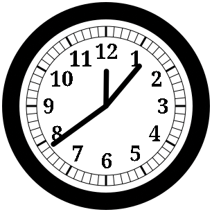 Figure 1: The results of the completed clock program.
For this article, I will use the Cairo [1] graphics library to draw the images. Cairo might not be the most intuitive graphics library at first, but it is ubiquitous: Once you know how to use it, you can quickly adapt to drawing with other libraries, such as the GTK [2] graphical user interface toolkit, which also uses Cairo.
Python is not the only programming language you can use with Cairo: Cairo was originally written for the C language, and so-called "language bindings" are available for most popular languages. For more on coding with Cairo, see the official Cairo documentation [3], as well as the exhaustive programmer's reference [4].
Before you begin, be sure you have both Cairo and its Python module installed. On Debian and its derivatives, you can verify that you have everything you need by running the command:
sudo apt install python3-cairo
A Quick Example
Before diving into how to draw the parts of a clock face, I will show you the basics required to use Cairo. In this example, I will draw an orange horizontal line into a PNG image file measuring 200 pixels square. The line will extend from the left-center edge of the image to the middle, thus spanning half of the image's width. The image is written to a file in the current directory called line.png. Listing 1 contains the program's full source code; Figure 2 shows the resulting image produced by the program.
Listing 1
line.py
01 #!/usr/bin/env python3
02
03 import cairo
04
05 surface = cairo.ImageSurface (cairo.Format.ARGB32, 200, 200)
06 context = cairo.Context (surface)
07
08 context.set_line_width (12)
09 context.set_source_rgb (1., .75, 0.)
10
11 context.move_to (0, 100)
12 context.line_to (100, 100)
13 context.stroke ()
14
15 surface.flush ()
16 surface.write_to_png ('line.png')
 Figure 2: An orange horizontal line, drawn with Cairo.
The first step in drawing using Cairo is to create an image surface. A surface is nothing more than a place on which to draw. Cairo can draw to many things: a temporary buffer stored in memory (known as an image surface), a PDF file, an SVG image, even on-screen to an X window [5], just to name a few. For all the examples in this article, I will have Cairo draw into an image surface in memory. Then when I'm done drawing to the surface, I'll instruct Cairo to write the contents of the surface into a PNG file.
surface = cairo.ImageSurface (cairo.Format.ARGB32, 200, 200)
This command creates an image surface, automatically allocating memory for a 200x200 pixel image with support for transparent regions of the image – known as an alpha channel, hence the letter A in cairo.Format.ARGB32.
The next step is to create a context for drawing onto the surface:
context = cairo.Context (surface)
Virtually all functions that draw using Cairo operate on the Cairo context, rather than the surface directly. The context keeps track of parameters used by drawing operations which follow. For example, to draw 12-pixel-thick lines in orange:
context.set_line_width (12)
context.set_source_rgb (1., .75, 0.)
The set_source_rgb () function deserves special attention. It sets the color with which to draw shapes. The parameters to the function are, respectively, the red, green, and blue levels of the color. A value of 1 indicates the maximum level of the color component; a value of 0 omits that color component from the color; and any value between 0 and 1 is a fraction of the color component's maximum intensity. Orange consists of red (1.), a somewhat lesser amount of green (.75), and no blue (0.).
Now it's time to draw the line:
context.move_to (0, 100)
context.line_to (100, 100)
context.stroke ()
This begins the line at the horizontal position (X) 0, ends it at the center of the image (an X position of 100 pixels), and centers the line vertically. Note that Cairo draws half of the line above the requested vertical position and half of it below; so the top of the line is actually positioned at the 94-pixel position and the bottom at the 106-pixel mark. This fact becomes important if you draw lines that are only a single pixel thick; at that point, an effect known as antialiasing comes into effect and can produce fuzzy lines (see the "Antialiasing" box).
Antialiasing
Since pixels are a fixed size, and an image is composed of only a limited number of pixels, shapes which are not perfect rectangles – or not perfectly aligned to an even pixel unit – cannot be represented perfectly in a digital image. To disguise these imperfections, a technique known as antialiasing is applied to the image. Antialiasing involves adding semi-transparent pixels around the affected areas of the shape, thus blurring the edges of the shape so as to cover up some of the imperfection. If the line is only one pixel thick, the edge is the whole line, so the line itself will look blurry.
Finally, make sure that all drawing operations are applied to the surface, and then write the contents of the surface to a PNG file:
surface.flush ()
surface.write_to_png ('line.py')
It is necessary to "flush" the surface first since Cairo often delays drawing to the surface; if a later drawing operation would draw over the top of a previous shape, there is no need to draw that previous shape in the first place, which could increase the efficiency of the program.
To try out this program, first ensure it is executable, and then run it:
$ chmod +x line.py
$ ./line.py
It should create a new PNG file in the current directory, with the contents as shown in Figure 2.
The Clock Background and Bezel
Now it's time to start drawing the parts of the clock, starting with the white background of the clock face, and the thick black bezel surrounding the clock. Both of these are circles; instead of drawing lines as I did previously, I will use Cairo to draw arcs, one filled with white, the other as a black outline.
In the previous example, I drew into a 200x200 pixel image. In this following example, where I start drawing the actual clock face, I draw into a 300x300 pixel image; 200x200 pixels is slightly too small to easily see all of the intricate details of a clock face. Keep this image size change in mind as you read on; for instance, the center of the image will be at 150 pixels rather than 100 pixels as it was in the last section.
Now, in addition to importing the cairo Python library, I need the math module as well:
import math
I need the math module because it provides a value for the mathematical constants pi and tau. As you will see shortly, I will use these constants to specify the extents of the arcs – in this case, I want full circles, so I will specify the extents as 2*pi radians, which is 360 degrees.
To draw the white background of the clock face, I use:
context.set_source_rgb (1., 1., 1.)
context.arc (150, 150, 150, 0, 2*math.pi)
context.fill ()
This draws the arc in white (1., 1., 1.). It centers the arc at the center of the image (the first two parameters to arc (), 150, 150), with a radius of 150 pixels (third parameter). It starts the arc at a zero-degree angle and draws all the way around to a full circle, or 2*pi radians (360 degrees). Instead of drawing a line encircling the arc, I instead fill the arc.
Instead of using pi and multiplying by 2, I could have used tau:
context.arc (150, 150, 150, 0, math.tau)
Using tau in lieu of pi may be advantageous to improve the efficiency of a program, as tau has already been calculated ahead of time; multiplying pi by 2 every time it is needed will require more computing resources. Graphics programs often involve a lot more math as they get more complex, and more math means more computing power required; improving efficiency can noticeably improve the speed of a more complex program.
Now I'll draw a 25-pixel-thick black bezel encircling the background:
context.set_source_rgb (0., 0., 0.)
context.set_line_width (25)
context.arc (150, 150, 137.5, 0, 2*math.pi)
context.stroke ()
Notice that the radius is not 150 pixels but 137.5 pixels. This is because I'm going to draw a 25 pixel band around the circle, and Cairo draws half of the "stroke" above the circle and half below. Hence I reduce the circle's radius by 12.5 pixels, half of the 25 pixel line thickness.
Listing 2 contains the full code required to draw the clock background and bezel. When run, it should produce a PNG file named clock.png, as shown in Figure 3.
Listing 2
clock-frame.py
01 #!/usr/bin/env python3
02
03 import math
04 import cairo
05
06 surface = cairo.ImageSurface (cairo.Format.ARGB32, 300, 300)
07 context = cairo.Context (surface)
08
09 context.set_source_rgb (1., 1., 1.)
10 context.arc (150, 150, 150, 0, 2*math.pi)
11 context.fill ()
12
13 context.set_source_rgb (0., 0., 0.)
14 context.set_line_width (25)
15 context.arc (150, 150, 137.5, 0, 2*math.pi)
16 context.stroke ()
17
18 surface.flush ()
19 surface.write_to_png ('clock.png')
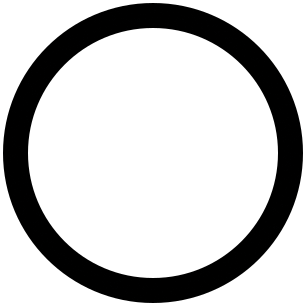 Figure 3: A skeleton of the clock, with the black frame and the white background.
Scalability and Transforms
So far, I have been supplying fixed dimensions to each of the Cairo functions I have used. From the width and height of the image, to the positions and sizes of each shape, I have specified exact, known numeric values, even pre-calculating them if necessary. But any serious program needs to deal with scenarios such as when the image dimensions change: If this program were added to a graphical user interface, it would generally make sense for the clock to change size as the user resizes the window. For this reason, I will rewrite the program such that the clock can scale to any image dimensions, even if the image is not square (i.e., the width and height are not equal). In addition, from now on, any additions to this program will be similarly scalable; throughout the remaining sections of this article, I will continue to write the program with as few fixed values as possible.
I still need to get the image dimensions from somewhere. As already mentioned, I could get them from the width and height of a graphical user interface window. For the purposes of this program, I will keep them as fixed values, but I will assign them to named constants, which I define at the top of the program (for clarity, I use the convention of printing the names of constants in capital letters):
IMAGE_WIDTH  = 300
IMAGE_HEIGHT = 300
The parameters to Cairo drawing functions, as well as calculations of all other parameters, will directly or indirectly involve one or both of these constants.
It should be theoretically possible to draw the clock into an image whose width does not match its height – once again, one example is if a user resizes the window containing the clock; it is highly unlikely that the user will resize the window to a perfect square. A conventional analog clock is a circle; if the program draws the clock to span the entirety of both dimensions of the image, and the image is not square, then the clock will be drawn as an oval. Besides being odd-looking, such an uneven clock also would make the mathematics of drawing the clock more complicated, especially drawing the hands. Therefore I have opted to draw the clock at a diameter equal to the smaller image dimension and center the clock on the larger dimension:
clock_diameter = min (IMAGE_WIDTH, IMAGE_HEIGHT)
clock_radius = clock_diameter/2
Most calculations that take place from here on will be relative to clock_diameter. I also calculate the clock radius here since it, too, will be used very often – clock_radius uses less space than clock_diameter/2 when printed in the magazine.
To center the clock on the image, I perform a translation, which is nothing more than an instruction to Cairo to add a specific amount to a dimension each time a drawing operation specifies a set of coordinates:
context.translate ((IMAGE_WIDTH-clock_diameter)/2, (IMAGE_HEIGHT-clock_diameter)/2)
Now, suppose I specify an image width of 400 pixels and an image height of 280 pixels. The image is wider than it is tall, so the program will draw the clock with a diameter of 280 pixels (equal to the image height). To center the clock on the image, half of the "extra" width of the image will be used as padding to the left of the clock, while the other half will appear to the right; that means all parts of the clock must be shifted over to the right by 400/2 - 280/2, or 60 pixels. The translate () function above tells Cairo that, from now on, the X component specified to all subsequent drawing operations in the program should be adjusted by 60 pixels. Thus, the following code, which draws the white clock face background, will draw the circle centered not at coordinates (140, 140) as you might at first expect, but at (200, 140):
context.arc (clock_radius, clock_radius, clock_radius, 0, 2*math.pi)
Without the translation, the circle would be centered at (140, 140), leading to a clock drawn on the left side of the image and a lot of empty space to the right.
Now, drawing the bezel requires more calculations. Previously, I specified the thickness of the bezel as a fixed width: 25 pixels. But if the clock grows or shrinks beyond its original diameter of 300 pixels, the bezel should correspondingly grow or shrink, or otherwise the bezel might look either too thin or too thick. A quick calculation reveals that a bezel thickness of 25 pixels for a clock that is 300 pixels in diameter is a ratio of 1:12; therefore, I now calculate the thickness of the bezel by dividing the diameter of the clock by 12; and while I'm at it, I similarly calculate the radius of the bezel:
bezel_width = clock_diameter/12
bezel_radius = clock_radius - bezel_width/2
Just as I replaced the fixed-value parameters to the Cairo function to draw the clock face background above, I also use the values just calculated as parameters to the functions to draw the bezel:
context.set_line_width (bezel_width)
context.arc (clock_radius, clock_radius, bezel_radius, 0, 2*math.pi)
In all other respects, though, the program remains the same as it was when it used the fixed values. Figure 4 illustrates the output of the program when I choose non-square image dimensions – in this case, 400x300 pixels.
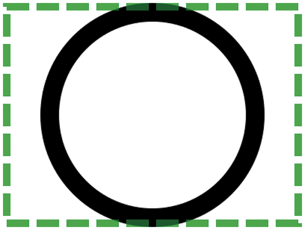 Figure 4: The clock frame, now that it can scale to any image dimensions. I have manually added a border around the boundaries of the image to more clearly demonstrate that the clock is horizontally centered on the image.
An analog clock face usually has two types of markings encircling it. The first are the lines to which the hour, minute, and second hands point. The other marks are the numerals denoting the hour. The numerals are simply a form of text, which involves some extra complications that I will not cover just yet.
The indicator lines, on the other hand, involve no drawing operations I haven't yet covered. The marks themselves are nothing more than lines, although most of the lines will be diagonal (I have so far only demonstrated drawing a horizontal line). Clocks usually have circles surrounding the marker lines, but these are even easier to implement, as they are simply stroked arcs much like the clock bezel.
Despite having previously made all other parts of the clock scale in size with the clock itself, I have opted to assign fixed thicknesses to the indicator markings, including the surrounding circles. There are 60 lines total, one for each second (or minute) to which one of the clock hands might point. One out of every five marks is drawn with extra thick lines, corresponding to the indicators for each of the 12 hours to which the hour hand might point. I have chosen to draw the majority of the marks and the surrounding circles with a line thickness of one pixel; the marks for the hour hand (the "major" marks) are drawn 3 pixels wide:
MARK_WIDTH = 1
MAJOR_MARK_WIDTH = 3
The length of the lines, however, should scale with the size of the clock. In addition, an analog clock usually has a small gap between the inside of the bezel and the marks, and this gap should scale with the clock also. For a 300 pixel clock, I find a gap of 10 pixels and a line length of 15 pixels to be aesthetically optimal, so I put the appropriate ratios into the program:
bezel_to_marks_gap = clock_radius/15
mark_length = clock_radius/10
At this point, and from now on, it is more convenient to specify the coordinates of objects to be drawn – lines, circles, and eventually the numerals – relative to the center of the clock, rather than relative to the top-left corner of the image as I have done so far. To do this, I apply another translation on top of the existing transformation:
context.translate (clock_radius, clock_radius)
Now, the coordinates (0,0) refer to the center of the clock; an X coordinate of clock_radius refers to the right edge of the clock, whereas an X coordinate of -clock_radius refers to the left edge. Likewise, a Y coordinate of clock_radius refers to the bottom edge of the clock, whereas -clock_radius refers to the top. Values in between refer to points within the inside of the clock face.
Next I calculate two new values, both of which are distances relative to the center of the clock. Each indicator marking on the clock is a line consisting of two points; as each one of these lines is mark_length pixels long, one of the points on each line is mark_length pixels closer to the clock's center than the other point:
mark_start_distance = clock_radius - bezel_width - bezel_to_marks_gap
mark_end_distance = mark_start_distance - mark_length
But these values are not just useful for determining the coordinates of each point of each indicator mark; I also use them to determine the radiuses of the inner and outer circles surrounding the indicator marks, which I will draw right now in single-pixel thickness:
context.set_line_width (MARK_WIDTH)
context.arc (0, 0, mark_start_distance, 0, 2*math.pi)
context.stroke ()
context.arc (0, 0, mark_end_distance, 0, 2*math.pi)
context.stroke ()
The next part, drawing the actual indicator marks, involves some mathematics. This part is executed inside a for loop that repeats 60 times, once for each mark; for each run of the loop, the variable i is incremented, starting with a value of 0 and ending up with a final value of 59. For each mark, I calculate the angle at which the mark is to be drawn. As I briefly mentioned earlier, a complete circle (360 degrees) is 2*pi radians; there are 60 marks on the clock, which means each mark is 1/60th of a full circle away from the previous mark:
angle = 2*math.pi/60 * i
I want to draw "major" marks (one mark out of every five) using thick lines, so I set the line thickness depending on whether i is evenly divisible by 5 (% is the mathematical "modulus" operator, which simply returns the remainder of a division operation on two numbers):
if i % 5 == 0:
  context.set_line_width (MAJOR_MARK_WIDTH)
else:
  context.set_line_width (MARK_WIDTH)
I know the angle at which each mark is to be drawn, but Cairo needs the start and endpoints of each line, so I need to figure that out. I want to draw the first mark at the very top of the clock, moving clockwise around the clock until there are no more marks to draw. Hence, the first mark should be horizontally centered and vertically at the extreme top of the clock; now that I have established all coordinates relative to the center of the clock, the X coordinates of the line should be zero, while the Y coordinates should be as negative as possible. As I approach a quarter-way around the clock, X should increase towards its maximum value, whereas Y should simultaneously increase towards zero. As I approach halfway around the clock, X should again decrease towards zero, and Y should continue to increase towards its maximum; by that point, the mark will appear at the bottom of the clock. This circular motion continues all the way around the clock (see Figure 5).
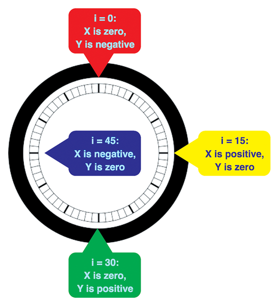 Figure 5: Visualizing the X and Y coordinates of the points that make up the lines of each clock indicator mark.
The mathematical functions sine and cosine, implemented in Python as math.sin () and math.cos (), are perfect for this purpose. Given an angle between 0 and 2*pi radians, math.sin () returns a value between negative 1 and positive 1: At an angle of 0 radians, it returns zero; at pi/2 (90 degrees), it returns 1; at pi, zero again; and at pi*3/2 (270 degrees), negative 1. At intermediate angles, it returns intermediate values in a smooth progression. Cosine is similar; it is effectively the sine of an angle offset by 90 degrees. The cosine of zero radians is 1; likewise, the cosine of pi/2 radians is zero, at pi, negative 1, and so on.
By multiplying the sine of the indicator mark angle by the distance from the clock's center to the start or endpoint of the mark, I can thus find the X coordinate of each point of the mark. Likewise, multiplying the negated cosine of the angle by the respective distance, I can find the Y coordinate of each point of the same mark:
context.move_to (mark_start_distance * math.sin (angle),
  mark_start_distance * -math.cos (angle))
context.line_to (mark_end_distance * math.sin (angle),
  mark_end_distance * -math.cos (angle))
context.stroke ()
With all of that said and done, the indicator marks and the surrounding circles have been drawn. Figure 6 illustrates the results of running the program.
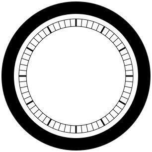 Figure 6: The clock face, bezel, indicator marks, and thin shroud encircling the marks. Take note that every five marks – the ones marking each hour – are thicker than the rest of the indicator marks.
The Hour Numerals
In the last section, I warned that drawing the numerals on the clock would be complex since it involves text handling. On the one hand, drawing text can get very complicated: Some languages draw their characters differently depending on the order in which the characters appear in the text (Arabic letters often connect together much like cursive in Western languages); text might consist of words from a language written from left-to-right mixed with words from a language written from right-to-left; and some Asian languages are written vertically. For such serious layout of text, it is a good idea to use a library such as Pango [6] to ensure all such complications are dealt with properly.
However, the numerals on a clock face are much simpler to draw: They are language-neutral (all languages print Indo-Arabic numerals 1 through 12 the same way). Therefore, I can get away with using Cairo's built-in text handling capabilities [7], which are simplistic enough that they are marked as a "toy API."
The first step is to define a list (actually a Python tuple) of strings, each corresponding to one of the 12 hour markings on the clock face. The 12-hour mark is conventionally placed at the top of the clock, so that mark will appear first on the list; the rest of the list is in increasing numerical order starting with 1:
NUMERAL_STRINGS = ('12', '1', '2', '3', '4', '5', '6', '7', '8', '9','10', '11')Of course, feel free to use any text strings you'd like, as long as there are 12 of them in the list and they are not too long; you might, for example, prefer Roman numerals over the Indo-Arabic ones I've chosen to use here. Figure 7 shows the clock with Indo-Arabic numerals.
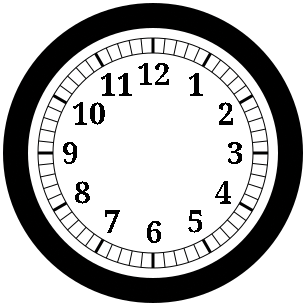 Figure 7: The completed clock face, showing the numerals denoting the hours.
Again, some distances need to be calculated relative to the size of the entire clock, so that all parts of the clock will scale properly. For a 300 pixel clock, I find a 10-pixel gap between the indicator mark lines and the numerals to be reasonable – the same distance I chose for the gap between the indicator marks and the clock bezel in the previous section. The numerals should be fairly large – they need to be easily readable – so I chose 30 pixels, or a fifth of the clock's radius, for the numerals:
marks_to_numeral_gap = clock_radius/15
numeral_size = clock_radius/5
The distance from the center of the clock to each numeral can be roughly calculated at this point, but the final position of each numeral has to be determined on a numeral-by-numeral basis, as the text for each hour marking may vary in height (some fonts display digits and many letters with descenders, among other inconsistencies):
numeral_distance = mark_end_distance - marks_to_numeral_gap
Next, Cairo needs to know the font and font size in which to subsequently draw text. Many clocks I have seen have the numerals drawn in a serif font; most serif fonts I've seen are quite thin, so I chose bold text to make the display a bit clearer:
context.select_font_face ('serif', cairo.FontSlant.NORMAL, cairo.FontWeight.BOLD)
context.set_font_size (numeral_size)
You may replace serif with sans-serif if you prefer, or even another generic font name such as monospace or cursive. Specific font names, such as Times New Roman, also work here, though a fallback font will be used instead if the named font you choose is not installed. Also, you may change cairo.FontSlant.NORMAL to a different setting, such as cairo.FontSlant.ITALIC, but in practice, I've never seen a clock with such styled hour markings.
The next part of the program operates in a loop to encircle the clock, much like in the last section when I drew the indicator mark lines. The main difference in this part is that this loop only cycles 12 times, since there are only 12 hour marks, instead of 60 second marks. But like in the previous section, the angle at which each hour mark is to be placed is calculated for each iteration of the loop:
angle = 2*math.pi/12 * i
x_multiplier = math.sin (angle)
y_multiplier = -math.cos (angle)
For efficiency, I have precalculated the sine and cosine of the angle and stored them in temporary variables; they will be used multiple times in the following calculations.
Now I will use Cairo to find out how wide and tall the text comprising the hour marking will be when it is drawn on the image – without actually drawing the text anywhere yet. This is because I need to know exactly where to position the text, and that depends on the final dimensions of the text:
extents = context.text_extents (NUMERAL_STRINGS[i])
Calculating where to position the text relative to the center of the clock certainly looks complicated, but it really isn't; it just involves a fair amount of arithmetic:
text_x = \
 numeral_distance * x_multiplier + \
 extents.x_bearing * x_multiplier - \
 extents.width / 2 * x_multiplier - \
 extents.width / 2
text_y = \
 numeral_distance * y_multiplier + \
 extents.y_bearing * y_multiplier + \
 extents.height / 2 * y_multiplier + \
 extents.height / 2
numeral_distance positions the text in the ballpark of where it needs to go. However, the text will vary in size from one numeral to another – 12 is definitely at least wider than a 1, and some fonts draw a 6 with a rounded part on the bottom, which they don't draw on a 2, for instance, so even the heights of the text strings are likely to vary. To properly center the text, the coordinates at which to place the text are adjusted by half the text's width (extents.width / 2) and half the text's height ( extents.height / 2). Sines and cosines range between negative 1 and positive 1, and Cairo needs to know where to position the top-left corner of the text, so I have to further subtract half the width (and height) from the coordinates. Finally, when Cairo draws the "extents" (dimensions) of the text, it tends to expect the coordinates to be relative to the bottom left corner of the text; the x_bearing and y_bearing contain adjustments to be made to the coordinates in order to obtain coordinates relative to where Cairo expects them to be.
Finally, draw the text at the proper position in the image:
context.move_to (text_x, text_y)
context.show_text (NUMERAL_STRINGS[i])
context.fill ()
Using context.stroke () in lieu of context.fill () would produce an outline or "silhouette" of the characters in the text, instead of normal "solid" characters.
The Hour, Minute, and Second Hands
I have now walked you through the steps and code required to draw all of the components of a clock face – from the bezel and white backdrop to the markings for each second and the numerals denoting each hour. However, a clock is not complete without a set of hands to indicate the current time. The hands consist of nothing more than a few lines and an arc (a semi-circle to be exact). In this section, I will at last complete the clock program by adding the code to draw the hour, minute, and second hands according to the current time.
To find the current time in Python, I use the localtime () function, which requires importing the time module built-in to Python:
import time
current_time = time.localtime ()
localtime () returns a Python object which, among other members, contains the current hour (tm_hour, ranging from 0 to 23, where 0 is midnight); the current minute (tm_min, ranging from 0 to 59); and the current second (tm_sec, usually ranging from 0 to 59, though very rarely it can reach 60 due to leap seconds). With these three values and some mathematics, I can calculate the coordinates of each component – line and arc – of each hand on the clock.
As with the other parts of the clock, I want the dimensions of the hands to scale along with the rest of the clock. For a 300 pixel clock, I find that hands with a width of about 8 pixels look good. I also like hour, minute, and second hands which, respectively, radiate 50, 75, and about 95 pixels out from the center of the clock. These dimensions are 1/20, 1/3, 1/2, and 5/8 of the clock's radius:
hand_width = clock_radius/20
hour_hand_length = clock_radius/3
minute_hand_length = clock_radius/2
second_hand_length = clock_radius*5/8
Once I know the current hour, minute and second, I need to calculate the angle at which to draw each of the hands. I convert the 24-hour time returned by localtime () to 12-hour time using a modulus of 12 (divide by 12 and find the remainder). From there, in theory, it should be simply a matter of converting the ranges of each of the values – 0 to 60 seconds, 0 to 60 minutes, and 0 to 12 hours – to fractions of 2*pi:
second_hand_angle = 2*math.pi / 60 * current_time.tm_sec
minute_hand_angle = 2*math.pi / 60 * current_time.tm_min
hour_hand_angle = 2*math.pi / 12 * (current_time.tm_hour % 12)
However, a real analog clock usually connects all three hands to the same rotor, gearing down each hand in such a way that the hands move at different rates. This means that the hour hand only moves 1/12 of the circumference of the clock when the minute hand makes a full circle; but the hour hand moves continuously, albeit barely noticeably, every time the minute hand – and, for that matter, the second hand – moves. I'll do the same with this clock:
second_hand_angle = 2*math.pi / 60 * current_time.tm_sec
minute_hand_angle = 2*math.pi / 60 * current_time.tm_min +second_hand_angle / 60
hour_hand_angle = 2*math.pi / 12 * (current_time.tm_hour % 12) +minute_hand_angle / 60
The code for drawing the hands is the same for each of the three hands – the only part that varies is the length of each hand (the hour hand is conventionally shorter than the other two hands at least). For this reason, I implemented the code for drawing a hand as a function, whose two parameters are the angle at which the hand should be drawn and the desired length of the hand:
def draw_hand (hand_angle, hand_length):
Inside the function, I calculate the coordinates for the points making up the hand. Each hand starts with a line as long as the desired hand length; the line is drawn half the hand's width from the center of the clock. The tip of the hand is drawn as an arc – a semi-circle to be exact – centered between the top of the first line of the hand and a second, mirror-image line to finish the hand:
x1 = hand_width/2 * -math.cos (hand_angle)
y1 = hand_width/2 * -math.sin (hand_angle)
x2 = x1 + hand_length * math.sin (hand_angle)
y2 = y1 - hand_length * math.cos (hand_angle)
xc = hand_length * math.sin (hand_angle)
yc = hand_length * -math.cos (hand_angle)
Now it's time to actually draw the hand:
context.move_to (x1, y1)
context.line_to (x2, y2)
context.arc (xc, yc, hand_width/2, hand_angle - math.pi, hand_angle)
context.line_to (-x1, -y1)
context.close_path ()
context.fill ()
Returning to the main part of the program, I call the function for each hand to draw – first the hour, then the minute, and finally the second hand:
draw_hand (hour_hand_angle, hour_hand_length)
draw_hand (minute_hand_angle, minute_hand_length)
draw_hand (second_hand_angle, second_hand_length)
Finally, I draw a circle over the center of the clock, with a diameter equal to the width of each hand:
context.arc (0, 0, hand_width/2, 0, 2*math.pi)
context.fill ()
Without the extra circle, the base of each hand would be drawn with flat lines, giving a less-than-eye-appealing "sharp" look to the hands (Figure 8). Compare Figure 8 to Figure 1, which does include the circle capping the rotor.
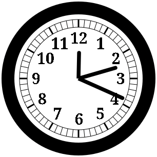 Figure 8: The clock, with the hands drawn without a circular "rotor cap" to conceal the sharp lines comprising the bases of the hands.
Listing 3 contains the complete code for the clock program. As already shown, Figure 1 illustrates the final result of the completed program. Obviously, the exact appearance of the clock will vary depending on the current time and your choice of fonts (for the numerals).
Listing 3
clock.py
001 #!/usr/bin/env python3
002
003 import math
004 import time
005 import cairo
006
007 def draw_hand (hand_angle, hand_length):
008         x1 = hand_width/2 * \
009              -math.cos (hand_angle)
010         y1 = hand_width/2 * \
011              -math.sin (hand_angle)
012         x2 = x1 + hand_length * \
013              math.sin (hand_angle)
014         y2 = y1 - hand_length * \
015              math.cos (hand_angle)
016         xc = hand_length * \
017              math.sin (hand_angle)
018         yc = hand_length * \
019              -math.cos (hand_angle)
020
021         context.move_to (x1, y1)
022         context.line_to (x2, y2)
023         context.arc (xc, yc,
024                      hand_width/2,
025                      hand_angle-math.pi,
026                      hand_angle)
027         context.line_to (-x1, -y1)
028         context.close_path ()
029         context.fill ()
030
031 # Replace the following with values of
032 # your choosing:
033 IMAGE_WIDTH  = 300
034 IMAGE_HEIGHT = 300
035
036 MARK_WIDTH       = 1
037 MAJOR_MARK_WIDTH = 3
038
039 # You may change this to the
040 # corresponding Roman numerals ('XII',
041 # 'I', 'II', etc.) if you wish
042 NUMERAL_STRINGS = ('12', '1', '2', '3', '4', '5', '6', '7', '8', '9', '10', '11')
043
044 clock_diameter = min (IMAGE_WIDTH,
045                       IMAGE_HEIGHT)
046 clock_radius = clock_diameter/2
047
048 surface = cairo.ImageSurface (cairo.Format.ARGB32, IMAGE_WIDTH, IMAGE_HEIGHT)
049 context = cairo.Context (surface)
050
051 context.translate ((IMAGE_WIDTH-clock_diameter)/2, (IMAGE_HEIGHT-clock_diameter)/2)
052
053 # Draw the background of the clock face
054 context.set_source_rgb (1., 1., 1.)
055 context.arc (clock_radius, clock_radius,
056              clock_radius, 0, 2*math.pi)
057 context.fill ()
058
059 # Draw the clock bezel
060 # (300 / 12 = 25 pixels)
061 bezel_width = clock_diameter/12
062 bezel_radius = clock_radius - bezel_width/2
063
064 context.set_source_rgb (0., 0., 0.)
065 context.set_line_width (bezel_width)
066 context.arc (clock_radius, clock_radius,
067              bezel_radius, 0, 2*math.pi)
068 context.stroke ()
069
070 # Draw the circles enclosing the
071 # indicator marking lines
072 # (150 / 15 = 10 pixels)
073 bezel_to_marks_gap = clock_radius/15
074 # (150 / 10 = 15 pixels)
075 mark_length = clock_radius/10
076 mark_start_distance = clock_radius - bezel_width - bezel_to_marks_gap
077 mark_end_distance = mark_start_distance - mark_length
078
079 # From now on, make Cairo interpret all
080 # coordinates we pass to it as relative
081 # to the center of the clock
082 context.translate (clock_radius,
083                    clock_radius)
084
085 context.set_line_width (MARK_WIDTH)
086 context.arc (0, 0, mark_start_distance,
087              0, 2*math.pi)
088 context.stroke ()
089 context.arc (0, 0, mark_end_distance,
090              0, 2*math.pi)
091 context.stroke ()
092
093 # Draw the indicator marks
094 for i in range (60):
095         angle = 2*math.pi/60 * i
096
097         if i % 5 == 0:
098                 context.set_line_width (MAJOR_MARK_WIDTH)
099         else:
100                 context.set_line_width (MARK_WIDTH)
101
102         context.move_to (mark_start_distance * math.sin (angle), mark_start_distance * -math.cos (angle))
103         context.line_to (mark_end_distance * math.sin (angle), mark_end_distance * -math.cos (angle))
104         context.stroke ()
105
106 # Draw the numerals denoting each hour
107 # (150 / 15 = 10 pixels)
108 marks_to_numeral_gap = clock_radius/15
109 # (150 / 5 = 30 pixels)
110 numeral_size = clock_radius/5
111 numeral_distance = mark_end_distance - marks_to_numeral_gap
112
113 context.select_font_face ('serif', cairo.FontSlant.NORMAL, cairo.FontWeight.BOLD)
114 context.set_font_size (numeral_size)
115
116 for i in range (12):
117         angle = 2*math.pi/12 * i
118         x_multiplier = math.sin (angle)
119         y_multiplier = -math.cos (angle)
120
121         extents = context.text_extents (NUMERAL_STRINGS[i])
122
123         text_x = numeral_distance * x_multiplier + extents.x_bearing * x_multiplier - \
124          extents.width / 2 * x_multiplier - extents.width / 2
125
126         text_y = numeral_distance * y_multiplier + extents.y_bearing * y_multiplier + \
127          extents.height / 2 * y_multiplier + extents.height / 2
128
129         context.move_to (text_x, text_y)
130         context.show_text (NUMERAL_STRINGS[i])
131         context.fill ()
132
133 # Draw the hour, minute and second hands
134  # (150 / 20 = 7.5 pixels)
135 hand_width = clock_radius/20
136
137  # (150 / 3 = 50 pixels)
138 hour_hand_length = clock_radius/3
139  # (150 / 2 = 75 pixels)
140 minute_hand_length = clock_radius/2
141  # (150 * 5/8 = 93.75 pixels)
142 second_hand_length = clock_radius*5/8
143
144 current_time = time.localtime ()
145
146 second_hand_angle = 2*math.pi / 60 * \
147                     current_time.tm_sec
148 minute_hand_angle = 2*math.pi / 60 * \
149                     current_time.tm_min + \
150                     second_hand_angle / 60
151 hour_hand_angle = 2*math.pi / 12 * \
152                   (current_time.tm_hour % 12) + \
153                   minute_hand_angle / 60
154
155 draw_hand (hour_hand_angle,
156            hour_hand_length)
157 draw_hand (minute_hand_angle,
158            minute_hand_length)
159 draw_hand (second_hand_angle,
160            second_hand_length)
161
162 # Draw the rotor cap in front of the
163 # base of the hands, to conceal the
164 # sharp edges of the lines which
165 # comprise the clock hands
166 context.arc (0, 0, hand_width/2,
167              0, 2*math.pi)
168 context.fill ()
169
170 # Write the result to a PNG file
171 surface.flush ()
172 surface.write_to_png ('clock.png')
Conclusion
In this article, I have shown you how to use the Cairo graphics library to draw computer graphics. I have demonstrated its use by walking you through all the steps required to draw an analog clock displaying the current time. This article only scratches the surface of what Cairo can do. For instance, you can draw Bezier curves, which are far more flexible in scope than arcs. Cairo can also draw shapes in colored gradients and other patterns more complex than solid colors. You also can save to other file formats in addition to PNG. I could have written the program to draw to SVG files instead. If you want to send output to a printer, look into Cairo's capability for producing output as PDF or PostScript. In a subsequent article, I will integrate the clock into an interactive graphical user interface program using the GTK [2] user interface library.
Infos
- The Cairo graphics library: https://cairographics.org/
- The GTK graphical user interface toolkit: https://www.gtk.org/
- A list of official Cairo documentation: https://cairographics.org/documentation/
- The official Cairo programmer's reference documentation: https://cairographics.org/manual/
- The X Window System: https://www.x.org/
- The Pango text layout and rendering library: https://www.pango.org/
- Documentation for Cairo's basic text rendering capabilities: https://cairographics.org/manual/cairo-text.html