Viewing wildlife with a Pi Zero photo trap

Garden Safari

© Lead Image © Diana Rich, Fotolia.com

© Lead Image © Diana Rich, Fotolia.com

Article from Issue 270/2023
Author(s):

Armed with no more than a Raspberry Pi photo trap, you can discover who pays a visit to your garden at night.

You might have a sneaking suspicion that wild animals are partying in your garden at night. If you want to know who's come to visit, I can show you how to set up a wildlife monitoring system that is based on a Raspberry Pi and can be completely tailored to your individual needs.

Photo traps are nothing new; you will find professional systems and small boxes for hobbyists online. I wanted one that was just as compact (Figure 1), but with more innovative inner workings. The Raspberry Pi control center shoots the photos with a connected camera. However, it only starts its work when a passive infrared (PIR) sensor, which registers the thermal radiation of living beings, detects motion. Afterward, the electronics revert to power-saving mode, so the photo trap can remain in the field for weeks.

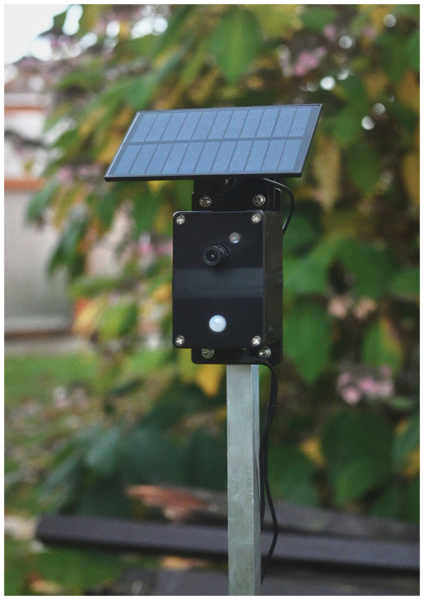
Figure 1: The photo trap automatically switches back to power-saving mode after a shot.

A Raspberry Pi Zero W delivers enough power and takes up so little space that everything fits into a compact case. To get the Zero W up and running, you need to download a new Pi OS image and transfer it to a microSD card. With a monitor and keyboard attached, you can get started by configuring the boot options and network settings.

You want to select automatic login over the command-line interface (CLI) with SSH enabled and then configure all the remaining settings in a terminal window from a computer on your network. The Pi Zero will have the hostname photototrap, which sums up its task. The next step is to create a separate folder for the project files in your home directory.

Functionality

When the camera is triggered by the PIR sensor, the image is written to the Pi Zero's SD card along with a timestamp in the file name. To check whether you have any new images, you can read the memory card on the spot or log the device into your home network and copy what you find there over a WiFi connection.

For the camera module, I decided on a model with a filter mechanism and photoresistor that responds to ambient brightness so I could take photos at night without IR blocking, as with a conventional Raspberry Pi NoIR camera, but also take photos in daylight that don't look overexposed; however, the colors are a little off. Ultimately, that does not make much difference, nor does the slightly lower resolution compared with the current Pi camera or the high-quality variant. As with other wildlife cameras, it's all about detection and documentation. The larger lens also does a good job of fitting into the body and adjusting the fixed focal length.

To remain functional for as long as possible in the wild despite a powerful battery and an optional solar panel, it's not a good idea to let the Raspberry Pi run constantly. Instead, you will want to wake it up with a small electronic system triggered by the PIR sensor and then switch it off again when the job is done (Figure 2).

Figure 2: The block diagram shows how the Pi Zero can be switched on and off.

The required software is included in the Python fotofalle.py script, which starts after booting the Zero, triggers the camera, and then shuts it down. The control electronics detect the sleep state by querying the Pi Zero serial port and shutting off the power supply completely. After that, only the frugal monitoring electronics of the photo trap remain active to react to the next motion detection event, which repeats the process. The script, a wiring diagram, and other useful information for building the device are available from my GitHub project [1], and English versions of the schematics can be downloaded from the Linux Magazine code site [2].

Structure

All of the hardware components integrate smoothly into a ready-made case with a rubber seal. The lid has a hole for the camera lens, the photoresistor, and the dome of the motion detector. A real-time clock is at the back of the lid, with an opening for the OLED display on the side. On the inside, I located the battery on the left, with the Pi Zero, charger board, and other electronics sandwiched to the right (Figure 3). The "Parts List" box summarizes all components.

Parts List

  • Raspberry Pi Zero W (1 or 2)
  • PIR sensor
  • RTC module
  • OLED display
  • Relay module
  • Battery
  • Overvoltage protection
  • Charging electronics
  • Circuit board, various resistors
  • Capacitor, diodes, transistor
  • Housing, wiring
  • Solar panel (optional)
  • IR spotlight (optional)
Figure 3: All components to be installed fit easily into a small housing.

On the protected underside of the housing, the photo trap has connections for a 5V power supply for external charging, an infrared light source, and the plug connection to the solar panel, which has an insert at the very top of the case and acts as a small canopy for rain protection.

One switch is integrated with the power supply. For longer periods without use, another switch disconnects the battery from the protective circuit and the charging electronics. A U bracket on the back of the housing accommodates a ground spike or strap to allow for other installation possibilities of the camera in the wild.

Real-Time Clock

The combination of a timestamp from the real-time clock (RTC) and a random string is used to tag the captured images. However, the Pi Zero does not have a built-in RTC and usually has to retrieve the correct time from a Network Time Protocol (NTP) server. To generate a timestamp for photos shot in the field, even without an Internet connection, you need to add additional hardware to the photo trap.

I used an RTC module with a DS3231 chip that can be powered from the 3V3 pin of the Zero. Older boards are designed for operation with a coin battery. If you want to use a conventional CR2032 cell, you have to remove the resistor at top right to avoid long-term damage. When running on a Raspberry Pi, you can optionally remove the pull-up resistors opposite the VCC pin.

Check the I2C bus with

sudo i2cdetect -y 1

and you will see two entries for the module. By default, the output contains the value 57 at position 50:7 and 68 at position 60:8.

You will need to enable the RTC during the boot process by adding the line

dtoverlay=i2c-rtc,ds3231

to your config.txt file for the overlay. The entry must not contain spaces to the right of the equals sign. After rebooting and calling i2cdetect again, a value of UU should now be found at position 60:8 (Listing 1), which confirms that the driver for the DS3231 chip is active.

Listing 1

Active Driver


Now that an RTC is running, you need to disable the previous service provided by the Raspberry Pi:

$ sudo systemctl disable fake-hwclock.service

After the next reboot, the Zero will use the hardware clock. Now you need to set up a udev rule to make sure the RTC is updated automatically over the web when an Internet connection is opened:

$ sudo nano /etc/udev/rules.d/60-rtc_synch.rules

This command creates the 60-rtc_synch.rules file with the content:

ACTION=="add", SUBSYSTEM=="rtc", ATTRS{hctosys}=="0", RUN+="/sbin/hwclock -s --utc"

As a result, the RTC should synchronize when the Pi Zero is briefly connected to the Internet and then will always display the current time when offline. You can check whether this is the case in the test setup at any time with:

$ sudo hwclock -r; date

If required, the built-in clock can be set manually:

$ sudo hwclock --set --date=" 10Dec 2022 10:00"

Now your photo trap has an independent and reliable clock onboard. In addition to the timestamp, the file names of the captured images include a random string, ensuring that no images are overwritten, even in the event of an error.

Buy this article as PDF

Express-Checkout as PDF
Price $2.95
(incl. VAT)

Buy Linux Magazine

SINGLE ISSUES
 
SUBSCRIPTIONS
 
TABLET & SMARTPHONE APPS
Get it on Google Play

US / Canada

Get it on Google Play

UK / Australia

Related content

  • Rasp Pi Fox Trap

    As a countermeasure to predators of rare ground-breeding birds, live traps are monitored by a microcontroller and a Raspberry Pi.

  • Photo Tools

    DIY tools and shell scripts can make for a smooth photographic workflow on Linux.

  • Raspberry Pi Pet Camera

    A Raspberry Pi, a Pi-compatible camera, and a mesh VPN are all you need to watch your pets from afar.

  • Automatic Fish Feeder

    Whether at work or on vacation, every pet lover worries about how to take care of their little roommates in their absence. What aquarium owners need is an automatic feeder.

  • Garden Irrigation

    With a Pi Zero and a few components, you can build an inexpensive and reliable automatic watering system for your plants in next to no time.

comments powered by Disqus
Subscribe to our Linux Newsletters
Find Linux and Open Source Jobs
Subscribe to our ADMIN Newsletters

Support Our Work

Linux Magazine content is made possible with support from readers like you. Please consider contributing when you’ve found an article to be beneficial.

Learn More

News