Technical 3D design using FreeCAD

Tutorials – FreeCAD

Article from Issue 224/2019
Author(s):

Designing simple shapes in OpenSCAD is easy, but if you want to print complex machines with multiple interlocking pieces, you need to bring out the big guns. That's where FreeCAD comes in handy.

In the last two issues [1, 2], I discussed designing 3D objects using scripts in OpenSCAD [3]. That was easy and fun, as well as an effective way of creating simple objects. But as soon as the number of faces and moving parts starts to grow, the lines of code multiply exponentially making your OpenSCAD designs unwieldy and difficult to troubleshoot.

Fortunately, FreeCAD [4] is a full-featured graphical software application that takes over from OpenSCAD for more complex printing. You can even import your OpenSCAD designs into FreeCAD (Figure 1)!

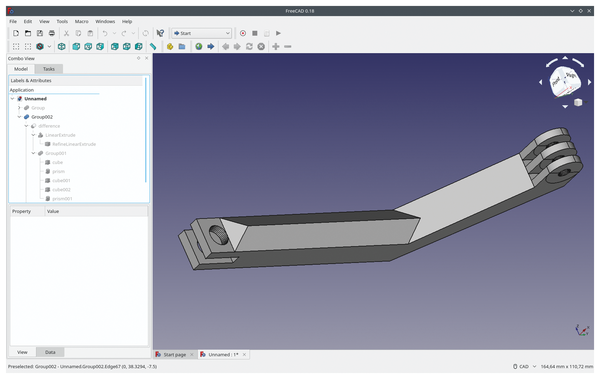
Figure 1: FreeCAD is a very complete CAD system that lets you import pieces from OpenSCAD.

Installing FreeCAD is easy enough: Most Linux distributions list it in their regular repositories. However, if you want an up-to-date version, something I strongly recommend, you will probably have to check out the "extra software" repositories (e.g., PPAs, AURs, or whatever).

FreeCAD also has an AppImage [5] of the latest stable version. I will be using the current version 0.18 in this article. There are also versions of FreeCAD that work on Windows and macOS.

Workbenches

One of the interesting things about FreeCAD is that, apart from your typical items-and-properties-on-the-left-workspace-on-the-right layout, it adds a third dimension to the interface: workbenches.

Workbenches are distinct areas especially designed for specific tasks within the 3D-design workflow. So, for example, you will have one workbench (with its own set of tools, especially designed for drafting pieces), another for turning the shapes into an actual 3D object, another for assembling several pieces together into a device, and another to produce the blueprints that you can share with a manufacturer.

There are also custom desktops for preparing a piece for 3D printing; for architectural design; for screws, bolts, and other fasteners; for rendering photorealistic (ahem!) images from your pieces; and so on. FreeCAD's modular nature means users can create their own specific desktops to scratch their own specific itches.

And create they do: When you open FreeCAD, there is a drop-down menu in the middle of the top toolbar, which shows more than 20 preinstalled desktops. You can acquire even more by going to Tools | Addon Manager from the program's menu.

However, knowing all this does not help you get any closer to actually producing a piece. Quite the contrary: The number of options and all the rules you have to follow to get a valid piece that will actually print is quite daunting.

Let's try and sort it all out with some examples.

Parts

If you want to jump right in, I'd recommend you start with the Part workbench.

From the start screen, pick Create new… (or press Ctrl+n) to create a new, blank project. Click on the workbench drop-down, choose Part, and you'll get something like what is shown in Figure 2 (sans the cube). To get the cube, click on the cube icon in the workbench's colorful toolbar, and it will appear in the workspace on the right.

Figure 2: The Part workbench lets you work with geometric primitives and use Boolean operations to shape complex pieces.

It must be said here that FreeCAD is quite stable, with the operative word in the prior clause being "quite." It has been known to happen that yours truly got carried away making a really complex piece and then… Poof! FreeCAD disappeared, taking a bunch of unsaved changes with it. FreeCAD does autosave, but, just in case, press Ctrl+s often.

Getting back to your piece, notice FreeCAD has also added a new cube item to the list of Labels & Attributes in the Combo View on the left. Click on it to highlight it, and the bottom box will fill with information regarding your cube. The View tab contains information about what the cube looks like: its color, opacity, whether it is visible or not, etc.

The Data tab contains information regarding its location, size, angle, etc. Click on Length, and you will be able to make a longer or shorter cube. Well, technically it wouldn't be a cube anymore, but rather a square-based straight prism, but you know what I mean.

Clicking on the Placement value will unfold it, and you can change the location coordinates, the angle, and the axis around which you want to spin your cube.

Talking of spinning, hold down Ctrl and then click and drag the cursor in the workspace to change the angle you look at your objects. Notice that there is also a guide cube in the upper right-hand corner of the pane with your object. It will tell you which side of your object is showing. You can also use the arrows surrounding the guide cube to change your view in 45-degree increments. You can change the view using the number keys: 1 being a view of the object from the front, 2 from the top, 3 from the right, and so on. 0 gives you an isometric view as shown in Figure 2. In the bottom right of the view, you can see the x, y, and z axes.

The little cube at the bottom right of the guide cube lets you change the view to Orthographic, Isometric, or Perspective and also gives you the option to zoom in on your object(s) until they fit in the pane. Another way to zoom in on one or all objects is by using the two left-most icons in the workbench's toolbar.

You can add more objects using the "solids" icons in the toolbar, and then adding or subtracting them from other solids to make more complex objects. For example, to make a hole in your cube, subtract a cylinder from it like shown in Figure 3.

Figure 3: Subtract a cylinder from a cube to drill a hole through it.

To do this, and assuming you haven't moved or changed the default size of the cube, click on the cylinder icon. The cylinder will appear at one corner of the cube, as both objects have their origin at the coordinate [0, 0, 0]. Select Cylinder in the Combo View on the left, and, in the properties box at the bottom, change its Placement to x = 5 mm, y = 5 mm, which will place it in the center of the cube. Also change z to -1 mm. Then change the cylinder's Height to 12 mm. The cylinder will now jut out 1mm over the top of the cube and 1mm below it.

To subtract the cylinder from the cube, you select both the cylinder and the cube from the list of items in the Combo View. You do this by first clicking on Cube in the list of items (the cube will turn green in the preview pane). Then, hold down your Ctrl key and select Cylinder. The image of the cylinder will turn green. Notice that when carrying out a Boolean subtraction the order is important! The second item you choose will be subtracted from the first and not the reverse way.

The Boolean operation icons are towards the right of the toolbar. Click the subtraction icon, and a hole will appear in your cube.

As with OpenSCAD, operations you carry out on bodies in FreeCAD are non-destructive. This means the cylinder is still there, but it has been hidden, and the cube can still be recovered intact. Unfold the Cut item that has appeared in the Combo View list on the left, and you'll still see both things there, but grayed out. To make them visible again, just select them and press the spacebar on your keyboard.

Another thing you can do is manipulate edges. You may have noticed in Figure 3 that the hole's edge is not sharp. It has a lip or, technically, a fillet around it. On your own perforated cube, mouse over the edge of the hole, and you will see it turn yellow. Click on it when that happens, and it will turn (and stay) green, indicating you have selected it. Find the Fillet icon in the toolbar (a bit more than halfway across, the fourth blue icon) and click it.

This will take you to the Tasks tab in the Combo View and will give you a list of edges to which you can apply the fillet. FreeCAD will have checked the checkbox next to the one you highlighted. Change the Radius at the bottom of the dialog (the fillet in the image has a radius of 0.5mm) and click OK at the top.

As you can see, FreeCAD presents a couple of differences from what you saw when working with OpenSCAD, not least that there is no coding involved. However, starting out with cubes and cylinders and adding and subtracting them is essentially what you do with OpenSCAD.

Where FreeCAD truly starts to mark differences is when it gets to part designing.

Part Design

By using basic geometric primitives, you can build more or less anything… if you are patient. However, FreeCAD offers a much easier and faster way of designing parts using, unsurprisingly, the Part Design workbench.

Let's build a real world piece to see how it works. In Figure 4, you can see the piece you will make (or at least how to partially make it). It is a button that broke on my microwave oven, and my wife asked me to 3D-print a new one. As it has to fit into holes and slots and things, its size and shape have to be very precise. You know what that means: Time to break out the calipers! Once you measure all the bits and pieces, it is time to get designing.

Figure 4: A replacement for a broken microwave button is a good and practical thing to practice designing.

Start a new project by pressing Ctrl+n and choose the Part Design workbench. Make a new part by clicking on the Create new body icon in the workbench's toolbar; it is the blue icon that looks like two steps, which is more or less a third of the way along the toolbar.

Since you should save often to avoid losing your work, press Ctrl+s and get that over with now. Give your project a name – something like button will work.

First, you will build the hull-like bit of the piece, which you do by sketching. Make sure the Body item in Labels & Attributes is selected, and click on the Sketch icon in the workbench's toolbar. The Sketch icon has a white background surrounding a red square and circle. It is immediately to the right of the Create new body icon.

Clicking the Sketch icon will take you to the Tasks tab. FreeCAD will ask you on what plane you want to sketch. As you want to draw the shape as seen from above, choose XY_Plane (Base plane) and click OK.

The workspace changes again. Make sure that, in the Edit Controls dialog in the Combo View, Grid snap is unchecked, but Auto constraints is checked. The rest of the options you can leave as they are.

Now you can start sketching. You are aiming for what you can see in Figure 5.

Figure 5: The basic sketch for your button.

Let's start with the curvy bit at the top of the button. Pick the arc tool (third tool from the right in the toolbar's drawing tools section), move your cursor into the drawing area, and move the crosshairs to where the x and y axes cross. You will see a red dot there. Hover the crosshairs over the dot, and the dot will turn yellow. A little red dot icon will also appear on the right and below your cursor. This is called a constraint and will link the center of the arc (one point) to the origin (another point). When both these things happen (i.e., the origin turns yellow, and the little red dot appears next to your cursor), click and place the center for your arc.

Move your mouse to the left, following the x axis more or less, until the radius is more or less 12mm long – it doesn't have to be exact. Keep the cursor on the x axis, and it will turn yellow, much like the origin did. Also, another little floating icon that shows a red dot on an arc shows up next to your cursor. That is another constraint. When you click to set the radius of the arc, it will attach the beginning of the arc to the axis.

You can apply constraints by hand, too. Move your cursor to the right, above the origin, and you'll draw the arc. Stop some point above the x axis on the other side of the y axis. Before touching it, click to set the end of the arc. Notice that, while the point at the beginning of the arc has a constraint symbol next to it, the point you just set for the end of the arc doesn't. Let's solve that.

First right click in any empty area of the drawing space to drop the arc tool. Then click on the endpoint turning it green. Click on the x axis, which also turns green. This is how you select multiple items in a sketch.

In the toolbar, locate the Fix a point onto an object constraint – it is the icon that looks like the constraint at the beginning of the arc: a dot attached to a curve. By clicking it, the end of the arc point will snap to the axis, and a little constraint symbol will appear next to it.

Constraints are important in FreeCAD, because they guarantee that you have considered every measurement and every angle. They guarantee that nothing has been left to chance in your piece, and that what you print will be exactly what you intended. When a sketch is fully constrained, it turns green. You can still work with an unconstrained (white) sketch, but I wouldn't recommend it.

Let's finish up constraining the semicircle. Click on the curve of the arc to select it (it will turn green). Locate the Constrain radius icon in the workbench's toolbar – the icon is a circle with a radius. Click it and a dialog pops up that lets you set the length of the radius. Set it to 12mm and press OK.

Notice how your sketch turns a bright lime green, indicating that it is fully constrained. On the left, in the Combo View, the Solver messages dialog will also display a text telling you that the sketch is fully constrained. Scrolling down the Combo View, you will see the Constraints dialog showing the constraints you applied to your sketch.

Use the line-drawing tool (to the left of the arc tool) to draw a line from the beginning point of the arc vertically down approximately 30mm. Drop the line-drawing tool (right click in an empty space within the drawing area), click on the line to select it, and constrain it by applying a vertical constraint to make sure it is perfectly vertical and a vertical length constraint, setting your line's length to exactly 30mm.

Draw another line from the endpoint of your arc downwards. Don't worry too much about the length. Drop the line tool and select the line. Constrain it to be perfectly vertical like your prior line. Then select your prior line and the new line, clicking first on one and then on the other so they are both dark green, and apply an equality constraint (the icon looks like an equals sign). This will make your second line exactly the same length as your first one.

Applying these constraints should make your sketch turn bright green again, indicating it is fully constrained. If this is not the case, check that the end vertices of each segment are joined, that you have applied vertical constraints, and so on.

To finish off the sketch, grab the line-drawing tools and draw a line between the ends of the two vertical lines, making sure you constrain the end vertices of your horizontal line to each of the end vertices of the vertical lines.

At the end of all that, compare your sketch to Figure 5 to make sure it looks the same.

To take your sketch back into the Part Design workbench, press the Close button at the top of the Combo View column on the left and you will see the white outline of your sketch. To make the sketch into a 3D object, press the Pad icon in the workbench's toolbar (the first icon on the left in the set of yellow icons). In the dialog box, type 8 mm.

To confirm your body is now 3D, move the cursor into the work area, hold down Shift, and right-click and drag. This will change your point of view of the object. You can also press 0 on your keypad, and see your object in an isometric view.

At the moment, it is a solid block. To hollow it out, click on the top face and again choose the sketch tools. This will let you draw a sketch directly on the part's face.

This time you are going to draw the inside shape of the button, which is the same as the outside, only smaller (see Figure 6). I have changed the color of the part, so you can clearly see your goal. You will be doing this in the reverse order from your previous sketch: You are going to start by drawing the bottom line. Give it a horizontal constraint, and then you are going to do something different: You are going to apply a constraint relative to an external geometry.

Figure 6: Sketching the inside shape of the button.

A constraint relative to an external geometry means that, instead of positioning a node or a line relative to the axis, origin, or another node or line in the same sketch, you position it relative to something on the face upon which you are sketching.

Pick the Link to external geometry tool from the toolbar (it looks like a blue box with a line with two end nodes floating above it). Move your cursor until it is hovering over the lower edge of the face with which you are working. The edge, normally black, will turn yellow. Click on the edge, and it will turn purple. The two end vertices of the edge will also appear as two purple circles.

Select the left-most vertex of that edge and the left-most vertex of your line and apply a vertical distance constraint of 2mm between the two. Select both left vertices again and apply a horizontal distance constraint of 2mm. Now select your line's right-most vertex and the right-most vertex of the object's edge and apply another horizontal constraint of 2mm between both.

Your line will turn green as it is now perfectly constrained relative to the object's face.

Now draw the lines straight up from the ends of your bottom horizontal line until you reach the x axis. If you are careful, draw straight up, and land on the axis, both the vertical and attaching-a-node-to-a-line constraints will snap in automatically. Draw a semicircle using the arc tool, snapping the center of the arc to the origin and the start and endpoints of the arc to the top vertices of the vertical lines. Again, with a little care, all the constraints you need will snap in automatically. If you have done everything correctly, your sketch will shine green as shown in Figure 6.

Close your sketch to go back to the Part Design workbench. Make sure your sketch is selected in the list of Labels & Attributes and pick the Pocket tool from the toolbar. The Pocket icon looks like a hollowed out blue box. In the Pocket parameters dialog that appears, choose Dimension from the Type drop-down, and change Length to 6mm before hitting OK.

All of this produces a part like what you see in Figure 7.

Figure 7: The hollowed out button.

You continue like this, mapping sketches to faces, constraining, and then creating new elements of your part with pads, pockets, and other tools until you have created the object you want. For example, to create the button's central column as shown in Figure 8, you pad a circular sketch on the inside face of the button. You then draw another circular sketch on the top of the column and make it a pocket, and so on and so forth.

Figure 8: The old, broken button on the right, with the new, 3D-printed version on the left.

Buy this article as PDF

Express-Checkout as PDF
Price $2.95
(incl. VAT)

Buy Linux Magazine

SINGLE ISSUES
 
SUBSCRIPTIONS
 
TABLET & SMARTPHONE APPS
Get it on Google Play

US / Canada

Get it on Google Play

UK / Australia

Related content

  • Designing your own stuff with OpenSCAD

    Ah! What a joy your first 3D printer … but once you have printed your first benchy, where do you go from there? To building your own pieces, of course!

  • FOSSPicks

    There's a collective groan in Graham's household whenever he gets a new device and finds a terminal prompt. The latest victim to his nmap skills is an LG OLED television!

  • Tutorials – 3D Printing

    Having covered several ways to design your 3D object, let's cover how we prepare your design for printing.

  • MySQL Workbench 5.1

    A small database is easy to plan on paper, but the structure quickly becomes more complex as you add more elements. MySQL Workbench can help you keep the tables arranged.

  • Printing Proper

    One last step remains in our 3D-printing voyage: actually printing something. This issue, we'll tackle how to print and monitor your print at the same time.

comments powered by Disqus
Subscribe to our Linux Newsletters
Find Linux and Open Source Jobs
Subscribe to our ADMIN Newsletters

Support Our Work

Linux Magazine content is made possible with support from readers like you. Please consider contributing when you’ve found an article to be beneficial.

Learn More

News