Change internal logic from relays to an Arduino

Redo

© Lead Image © donatas1205, 123rf.com

© Lead Image © donatas1205, 123rf.com

Article from Issue 260/2022
Author(s):

An electronic project at a local science center was showing its age, calling for a refresh: in this case, rebuilding it almost from scratch with an Arduino instead of relays.

A museum exhibit called Buzzwire looks like outlines of two oversized hands giving you a high five (Figure 1). Each hand has a metal handle with a loop, and your goal is to move the loops up and down the hand without touching it. For an even bigger challenge, you can try to do both hands at once in the same or opposite directions. If either loop touches the hands, a buzzer and light come on and the handle vibrates.

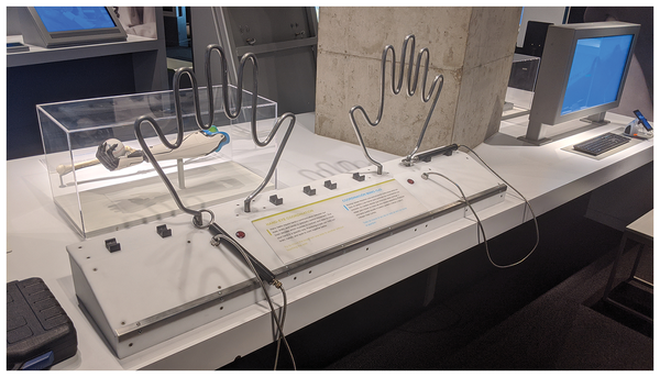
Figure 1: The Buzzwire exhibit (after the rebuild).

The original circuitry for the hands comprised interconnecting timer relays to switch the assorted components. The design had no microcontrollers or anything smarter than a switch, which had several drawbacks – but the main one was that if the puzzle was abandoned mid-run, the light, buzzer, and vibration motor would run continuously until the handles were removed.

Because one of the components had burned out on more than one occasion, the decision was made to rework the exhibit with upgraded technology that addresses some of its problems.

New Tech

To design the new controller, I started with an Arduino Mega because I had one on-site. An Arduino Uno would have worked just as well, but in this case, the Mega is a standard part, is easy to trade out, and is kept in stock. (See the "Physical Rebuild" box.)

Physical Rebuild

While I rebuilt the control electronics, I sent the case out to be rebuilt as well. The original design was made out of plywood and had started to accumulate a lot of dings and scratches. The case rebuild was very helpful because it showed areas that needed to be reinforced. Ultimately, I had the entire front panel replaced with Delrin, a very hard plastic that will withstand wear and tear better than plywood. It also brings a fresh look for anyone that has seen it before.

The physical rebuild also incorporated larger vibration motors in the handles. The old version used pager motors, which were more heard than felt. The machine shop I worked with fabricated new handles from scratch that incorporated larger motors, making the buzz much more noticeable.

I started by assigning pins on the Arduino. The handles each need an input pin, so I started with those. Other than timers the handles are the only inputs to the circuit design. For outputs, I wanted several things to operate with different timing, so I set up four pins to control relays, which will handle both the assorted voltages and the ability to switch things on and off at different times (Table 1; Figure 2).

Table 1

Arduino Connections

Pin

Connection

2

Left handle input

3

Right handle input

8

Relay 1 control signal

9

Relay 2 control signal

10

Relay 3 control signal

11

Relay 4 control signal

GND

Left hand (puzzle)

GND

Right hand (puzzle)

GND

Relay board ground

5V

Relay board power

Figure 2: The wiring diagram includes relay and barrier strip connections. All connections were brought out to a barrier strip for easier servicing.

Finally, for ease of connections into the exhibit itself, I assembled everything on a piece of plywood and brought all of the connections to a pair of barrier strips (Table 2). Each hand got its own barrier strip, and the two are identical except for power input on connections 11 and 12.

Table 2

Barrier Strip Connections

Connection No.

Left Barrier Strip

Right Barrier Strip

1

Hand (sculpture)

Hand (sculpture)

2

Handle

Handle

3

Ground (1)

Ground (1)

4

Ground (1)

Ground (1)

5

Ground (1)

Ground (1)

6

12V (switched) (2)

12V (switched) (2)  

7

12V (switched) (2)  

12V (switched) (2)  

8

12V (switched) (2)  

12V (switched) (2)  

9

Ground

Ground

10

5V (switched)

5V (switched)

11

Ground

Ground

12

12V power in

5V power in

(1) Interchangeable ground terminals. Choose one.

(2) Interchangeable 12V terminals. Choose one.

Logic Flow

Now that all of the hardware was assembled and simple test programs tested the activation of the relays, which in turn vibrated the handle or turned lights and buzzers on and off, I needed to figure out the flow of the control program.

One of the things that is often overlooked in a project is documentation. So as not to fall into that trap, I made copious notes and typed them up into a documentation package. One of the things I included was a flowchart to describe the logic (Figure 3; see the "Flowcharts" box).

Flowcharts

Flowcharts are an excellent way to visualize flow through a system, program, or other process. In the early days of computers when programs were built on punched cards and you "programmed" on paper, they were an essential tool to understand flow. Although still useful for design, they aren't at the forefront, as they once were. Flowcharts are seeing a resurgence, though, in online forms where data moving through a system is now visualized in the flowchart style that once originally designed it.

Figure 3: A flowchart is a handy way to visualize what you want your code to do – or show what your code does, once it's written. Note that some functions are called multiple times, even if the task the function accomplishes is already in the tested state.

Walking through the flowchart, the first decision is the diamond right below Start asking whether the ring is touching the puzzle. If not (exit to the right), you wait 250ms, turn off the relays, and return to the original decision. It should be noted that Turn relays off will happen even if they are already off.

If the ring is touching the puzzle (exit the decision through the bottom), then turn the relays on. The next decision diamond checks whether the relays have been on for more than 10 seconds. If so (exit right), you turn off the relays and return to the first decision. If not (exit bottom), just return to the first decision.

That process will loop infinitely until power is removed from the Arduino. You should also note that this flowchart shows a simplified process. I don't specify assigning variables or duplicating the process for both hands, just the theory of operation about what's happening inside the logic. In this way, the program flow is easy for even a non-programmer to follow.

Code

Arduino code is made up of two sections. The setup section runs once when the Arduino powers up, and the loop section then runs infinitely until power is removed. As their names imply, they are designed to initialize everything and then run continuously.

Buy this article as PDF

Express-Checkout as PDF
Price $2.95
(incl. VAT)

Buy Linux Magazine

SINGLE ISSUES
 
SUBSCRIPTIONS
 
TABLET & SMARTPHONE APPS
Get it on Google Play

US / Canada

Get it on Google Play

UK / Australia

Related content

  • Perl: Arduino Project

    With a few lines of self-written firmware and a simple Perl script, Perlmeister Mike Schilli trains one of his Linux computers with a plugged in Arduino board to switch electrical equipment on and off using a relay. Enchanting.

  • Python’s Tkinter Library

    Use Tkinter to control your Rasp Pi projects from a smartphone or tablet.

  • Serial Communications

    We explore serial communications, from the electrical specs to protocols and libraries, with an example of serial communication with an Arduino.

  • Escape Room Puzzle

    A digital puzzle presents a challenge for young people in an escape room.

  • PySimpleGUI

    Use the same code for your Python GUI and web apps.

comments powered by Disqus
Subscribe to our Linux Newsletters
Find Linux and Open Source Jobs
Subscribe to our ADMIN Newsletters

Support Our Work

Linux Magazine content is made possible with support from readers like you. Please consider contributing when you’ve found an article to be beneficial.

Learn More

News