
Change internal logic from relays to an Arduino
A museum exhibit called Buzzwire looks like outlines of two oversized hands giving you a high five (Figure 1). Each hand has a metal handle with a loop, and your goal is to move the loops up and down the hand without touching it. For an even bigger challenge, you can try to do both hands at once in the same or opposite directions. If either loop touches the hands, a buzzer and light come on and the handle vibrates.
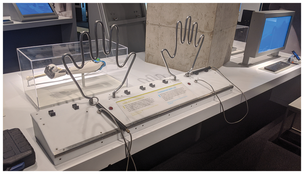 Figure 1: The Buzzwire exhibit (after the rebuild).
The original circuitry for the hands comprised interconnecting timer relays to switch the assorted components. The design had no microcontrollers or anything smarter than a switch, which had several drawbacks – but the main one was that if the puzzle was abandoned mid-run, the light, buzzer, and vibration motor would run continuously until the handles were removed.
[...]
Buy this article as PDF
(incl. VAT)
Buy Linux Magazine
Subscribe to our Linux Newsletters
Find Linux and Open Source Jobs
Subscribe to our ADMIN Newsletters
Support Our Work
Linux Magazine content is made possible with support from readers like you. Please consider contributing when you’ve found an article to be beneficial.

News
-
UN Creates Open Source Portal
In a quest to strengthen open source collaboration, the United Nations Office of Information and Communications Technology has created a new portal.
-
Latest Linux Kernel RC Contains Changes Galore
Linux kernel 7.0-rc3 includes more changes than have been made in a single release in recent history.
-
Nitrux 6.0 Now Ready to Rock Your World
The latest iteration of the Debian-based distribution includes all kinds of newness.
-
Linux Foundation Reports that Open Source Delivers Better ROI
In a report that may surprise no one in the Linux community, the Linux Foundation found that businesses are finding a 5X return on investment with open source software.
-
Keep Android Open
Google has announced that, soon, anyone looking to develop Android apps will have to first register centrally with Google.
-
Kernel 7.0 Now in Testing
Linus Torvalds has announced the first Release Candidate (RC) for the 7.x kernel is available for those who want to test it.
-
Introducing matrixOS, an Immutable Gentoo-Based Linux Distro
It was only a matter of time before a developer decided one of the most challenging Linux distributions needed to be immutable.
-
Chaos Comes to KDE in KaOS
KaOS devs are making a major change to the distribution, and it all comes down to one system.
-
New Linux Botnet Discovered
The SSHStalker botnet uses IRC C2 to control systems via legacy Linux kernel exploits.
-
The Next Linux Kernel Turns 7.0
Linus Torvalds has announced that after Linux kernel 6.19, we'll finally reach the 7.0 iteration stage.